Sunday, November 15, 2009

Summary


I was very nervous and to be honest quite unsure as to wether my final design would work. As my chair basically used up the entire piece of xanita, this meant that I was unable to get it laser cut at the workshop but instead would have to cut it myself. To try and make life a little easier I printed out my autocad plan on 25 A3 pages and stuck them onto the xanita with masking tape. Having my lines to guide me I started to cut. Having been cutting on my hands and knees for the past 6hrs I was tired, sore and running out of patience. Wether it was a mix between this, the fact that I just changed blades or that I had left the xanita in the glaring sun for a good part of the day, I am unsure, but as I was doing some of my 45degree cuts as well as cutting through to the outer layer the material ripped- and well that was that. I was quite upset, as I had not ONCE cut through the material on my practice piece. In the end I had to use masking tape to hold some of the edges together. The join, which was meant to bolt down the armrest, also snapped off at the fold, so I don’t advise leaning back! All in all I was actually quite happy with my design, as I believe that with another piece of xanita my chair would be “hole proof” and do it’s job more proficiently.

Branding and Context

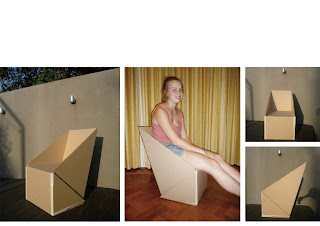
I believe that my final design meets the needs of the user as it complies with it’s initial purpose for being an outdoor chair where patrons can relax for a moderate period of time. As shown below the low seating allows the legs to be spread out, essentially taking the weight off the feet. The slanted backrest gives support to the lower back and allows the body to comfortably lean back. The small size of the chair means that it can be easily moved around and does not take up large quantities of space. The text on the side of the chair is a simple but effective form of branding to advertise the event.

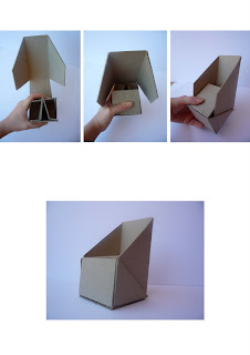
Chair Assemble

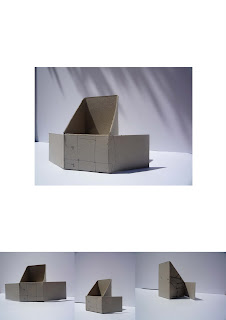
Chair Plan and Elevations

Saturday, November 14, 2009

Final Template


First Xanita Model


It was now time for the xanita board! Having received my first piece in class I decided to get it laser cut in two pieces as the maximum surface area that could be cut in the uni workshop was 1200mm x 1500mm. I decided to cut it along the fold line of where the backrest and arms joined the base of the chair. As I didn’t look at the exact measurements on cad before cutting it, but instead going off my print out in my journal my cut was 80mm off and therefore the backrest was not at its full length- which wasn’t really design issue, it just looked incorrect aesthetically. Once it was cut I suddenly realized that I really hadn’t considered the thickness of the xanita at all and that I had some design problems that needed to be consolidated.

1. As I began to do my 45 degree cuts and folds it occurred to me that many of my lines were off and that a lot of my measurements needed to be altered by about 10-20mm.

2. A problem that soon arose was that the armrests needed to fold into the base of the chair so that it sat flush across the front. In order for this to happen the xanita needed to be cut back to its outer layer so that the arms could slot in. Though as this was a corner piece there was a high chance that the material would rip at the seams.

3. The biggest problem was that I hadn’t really considered the mechanics behind the backrest. Its only connection was at the base of the chair, which meant that when pressure was put on it there was nothing to stop it from falling back. Unsure as to how I had missed this crucial detail the first time, I started to devise locking system out of xanita scraps to work out how this problem could be solved. Having designed two 50mm wide tabs that folded inwards and joined at the centre of the chair I was now ready to make my final chair.


Wednesday, November 4, 2009

Concept Refinement


Having made my second 1:1 model in class I was finally satisfied with my design. Though when I sat on it the following day to photograph it I realised that my design had some flaws as it struggled to hold my weight. Although the material was only 2mm thick (which was the main reason behind it’s fragile structure) I could also notice some problems with the locking system. The detachable slot was only 112.5mm in width, which weakened the lock when pressure was put on the seat. What I really needed was a slot that was 300mm wide so that it reached from the seat to the floor. Though in order to do this I needed to make some alterations to my design, as I did not have enough card left to make these changes. In the end I decreased the width of the “fold under” flaps from 75mm to 30mm and created an “L shape” which hooked under and into the seat flaps. Small alterations were also made to the dimensions of the chair arms and seat. After testing the alterations on a 1:5 paper model I then went on to make a 1:1 model from mount board. In conclusion I am very happy with my final design and am now ready to test it on the xanita board!!!


Evaluation


I have decided to evaluate my progress over the past 6weeks to see how my design has progressed over this short period of time. The photograph illustrates my three 1:1 chairs from week 6, week 10 and week 12. I have also sketched the locking systems for each chair to help demonstrate the evolution of my design.

The week 6 chair shows a relatively pleasing aesthetic from the photograph, but from the sketch it is noticeable that there is no locking system to support the seat and the only reason the chair could hold my weight is from the excessive amount of material used that was double and sometimes triple folded to create a fairly sturdy structure.

The week 10 design was cut from a 1800mm x 1200m piece of cardboard and therefore gives a more accurate idea of scale. As a result in comparison to my design in week 6 it is 100mm lower to the ground. From looking at the sketch it is apparent that a locking system has been derived, though the solitary triangle does not give the seat enough support to withhold 150kg.

The current design (week 12) aesthetically is almost identical to the week 10 design, except for the leaning backrest that sits at an approximate angle of 60degrees. The week 12 sketch shows a vast improvement in the structural support of the chair with the use of a sturdy gridlock.

Although I am very pleased with my improvement over the past few weeks I still believe that I am able to derive a more thorough locking system that supports the seat right through to the ground. I am therefore going to further refine my concept to create one more 1:1 before I begin with using the xanita board.

Tuesday, November 3, 2009

New Concept


After many hours and MANY cardboard 1:5 models I have come up with a new concept, one that I am much more satisfied with. This design still basically follows the same aesthetics as the previous but has a slanted backrest, which allows the body to be in a more relaxed and comfortable position. I have also generated a much more effective locking system to support the seat, as I quickly learnt after falling through the seat of my last 1:1 model, that my previous seat structure was inadequate.

Sunday, October 25, 2009

Further Development

This concept has starting to initiate a structural support for the seat. I have created two slots in the base of the chair so that the two folded sides of the seat have something to insert into, though as the board is only 2mm thick this idea did not prove to be very successful. Though the slotting of the back rest into the seat (which can be seen on the side view below), is effective both visually and functionally.


Concept Development

Now that I am at the stage of concept development I have moved onto using 2mm mount board at a 1:5 scale. In comparison to the paper, the cardboard is not as flexible and at a 1:5 scale it is more truthful to the characteristics of the xanita board.

This design follows on from my “beach chair” in concept 3. As I have been having some trouble initiating my design I have decided to take a look back at the chair I designed in week 6 to get some inspiration. Though unlike my last design, this time I must be much more efficient with my use of material as I am restricted to a 1220mm x 1830mm sheet of xanita.

From this design I was able to come up with a general aesthetic for my chair, which includes a 300mm high seat with a 400mm high backrest. Though the structure of the chair is still in the stages of development as the seat has no form of support and therefore a locking system still needs to be devised.


Research: Beach Chairs


Chair One:

I like this lounge as it is low to the ground, has a low back rest and has an outstretched seat which allows the person to stretch out their legs. The lounge has been cleverly designed so that it can be folded up and carried around. If I could incorporate this into my chair, it would be a great form of branding. The disadvantage for this chair is that I am restricted to a 1220mm x 1830mm piece of xanita board, which means that the prospect of making a lounge chair is almost impossible.

Chair Two:

This chair has low seating with an adjustable high backrest. When propelled up (as shown in the picture) the person is sitting almost directly upright. The armrests are practical for when the person is sitting upright, otherwise are simply used to function the adjustable backrest. Once again the restriction of material means that a high backrest may not be suitable, though the arm rests could be something I could incorporate into my design.

Chair Three:

This is another beach chair with a more simplified design. The low to the ground seating allows the person to outstretch their legs in a comfortable manner and the low backrest creates a somewhat lounge position. This chair also complies with the material restrictions.

Concept Three- Development

I have decided to further develop concept three, as I believe it best responds to the lack of seating at 100% Tokyo Design. The low seating outdoor chair will allow visitors to comfortably sit outside on the expansive lawn area. Essentially this will help to de-compact the already busy atmosphere inside the tents. It an be seen from the photograph in my concept three development that many visitors have chosen to sit on the lawns to eat lunch or to simply rest their feet, therefore my design will be of purpose by providing more comfortable seating and essentially encourage more people to sit outside.

Monday, September 14, 2009

Be4U- Furniture Design History


NGV Visit

Exemplar- Shigeru Ban


The Japanese Architect Shigeru Ban is infamous for his use of paper where many of his works primarily rely on this inherently weak material to form the structure of the building. The paper can be manipulated into a variety of shapes such as tubes, honeycomb panels and membranes to create sturdy well-developed structures. In doing so Ban overtly challenges the relationship between strength and sustainability where he explores the innate characteristics of specific materials.

Emergency Shelters in Rwanda

-       Ban designed three prototype shelters that primarily used paper tubes as the frame and a plastic overhead sheet for weather protection. This design was not only ethical in principle as it was inexpensive and easy to transport but it also solved an important environmental issue as refugees had

Image 2&3

 
previously been forced to cut down trees to build their shelters creating massive deforestation problems.

The Japan Pavilion for the Hannover Exhibition

-       Was constructed from a grid-shell structure of three-dimensional curves that were constructed from paper tubes. A recyclable paper membrane was constructed for the roof. Unlike the common membranes that incorporated the substance PVC that emits toxins when burnt, Ban invented unique water resistant and fire retardant paper roofing, which could be correctly disposed of.

Esquisse Four- Understanding Form


This week’s task was a lot of fun! Having formed groups in class we endeavoured to find a solution to the task at hand, which was to create a structure that would support the weight of a person. Having created a locking system in the previous weeks task I had an idea in my head as to what I wanted to achieve. Though this time it was not as simple, as the scale was a lot larger and ideally we wanted to create a back to our chair. We started off doing some sketches where we experimented with the idea of a grid system, but I soon moved on the paper as I found it an easier tool to work with.

The paper ended up being simply easier to configure in comparison to the cardboard, as I found the thin material was more flexible at a small scale. About half way into the class I began to construct a square pattern that solely relied on the concept of folding. I found the fold to be very sturdy and as I played around with the squares it turned out to be quite effective. Back at home after class I came up with a pattern that was derived from squares and triangle that folded together to create a chair with a back and arms, which took a similar form to the standard ‘sofa’. The pattern was then transformed into a 1:1 scale where the squares were 400mm x 400mm.

Materials which helped me along the way was the masking tape which proved to be a saviour in disguise, as it allowed me whilst I was designing with paper to stick squares together where a fold was needed instead of having to cut out the entire pattern again. The metal ruler was fantastic for scoring the cardboard to create a fold and the measuring tape proved to be handy when ruling lines at a large scale. Though when trying to shove bicycle boxes into my sisters Nissan, I could have done with a larger car!

All in all, I thought it was a successful project and a comfortable chair! 

Esquisse Two- Understanding Form


I found this task quite challenging and in the end had to surrender to a “not so perfect” design. At the beginning I tried to create a system that only relied on one join as I could foresee that the locking system being trailed around me was not going to hold the four sides together. Although it is wise to put “pen to paper” before “knife to card”, I found that a little too much thinking was simply a good waste of time and that sometimes it is best to just make the mistake and then subsequently learn from it.

After looking at the clock and realizing that two hours had passed and I had absolutely nothing to show except for a few lines and numbers that were of little use, I subsided to the four sided joining system. Frustrated and annoyed mixed in with a rapid loss of concentration I decided to talk to “the friendly man sitting in the corner” who was completing his masters (sorry, can’t remember his name). He suggested that perhaps I should tackle it from the inside rather than the outside.

After leaving class I experimented with a few locking systems that worked from the centre of the pyramid rather than the four sides. Finally I came up with a two-piece triangle that interlocked and mounted to the base of the pyramid. Once in place the mini triangle had four “keys” that individually locked into the “keyholes” on the four sides of the pyramid.

In theory the locking system worked but in the end what let me down was a “not so perfect” pyramid design, which I think was perhaps a result of slighting off measurements or untidy cutting.  

Esquisse One: Understanding Material


This week’s task was all about PRACTISE, PRACTISE, PRACTISE! The task at hand was to create a cube using four different folds. A concept I had originally thought to be rather easy turned out to be more time consuming than I’d thought. After hacking away at the cardboard for a good hour, I soon realised that precision and neatness was the key, as 1mm out could be the difference between a 90degree angle and an 80degree angle. After testing the more “difficult” folds several times I decided to take the plunge and use my last piece of cardboard.

My final cube in the end was quite successful, not quite perfect as one of the sides ended up being a few mm longer than the other three, but none the less a good start! 

Esquisse Three- Locking Systems


I really enjoyed this week’s task and it was the quickest one I’ve completed to date! I originally started off creating a triangular corrugated system that interlocked. I then realised that a complex design was really not necessary and that a simple join created a sturdy lock. From here I expanded my idea by encapsulating this join within a box, to then realise that the join itself made the box weaker as it meant that slits had to be cut in the centre of the object. Having done a full circle in the span of 1hr I scrapped the joining system and focused on the method of folding to create a sturdy box.

Having achieved a simple folding system all that was needed now was something to hold it together. Having made two semi-circles on either side I cut a strip of cardboard to create a band that wrapped around half the box and folded over both the holes. The band worked really well in that the band was held in place by the tight fold of the box.

All in all I thought this weeks design was quite successful and all though I may not weigh 100kg, it was pretty damn strong!